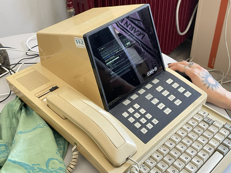
Northern Telecom Displayphone NT6K00
During our initial Houweling Telecom Museum trip with the class, I got this Northen Telecom DisplayPhone from their trash pile. At the museum there is space underneath their staircase where they pile old devices that they no longer wish to keep in the museum. I picked this first one up and kind of messed around with it instead of trying to fix it. So if you're looking into fixing a DisplayPhone here are some links that can provide some guidance:
- Northern Telecom DisplayPhone NT6K00 Tour & Tune-Up
- A forum with a loooot of information about how to fix one.
For more information about the Displayhone: Info and specs of the Displayphone from the York Museum's website or my favorite: Daves Old Computers entry for Displayphone
For me this was really the start of feeling more confident around cables and connections and soldering. Even though I already messed with it before, I still felt insecure about soldering especially soldering things together to make them actually work...
Process
I started with emptying out the displayphone, I decided that I want to make a fortune teller and thought it is a good idea to tear the whole thing apart and then use the bits and pieces to create like a bone throwing chance game that is also like fortune telling. I started learning about the components and looked into Open Circuits that our tutors Imane and Martino brought by.
After learning about some of the parts, and the dangers of touching a capacitor, I abandoned this idea, it didn't really feel fun or interesting to me anymore. What was really interesting to me was the fact that one of the writes of this book is a repairer who also stumbled upon his own DisplayPhone! Here is his log on twitter.
After looking at his process and researching ways in which the displayphone can be resurrected, I decided to make it into what kids call nowadays a cyber deck :P
Reverse Engineering the keyboard
Fred and I dismantled the keyboard, stripped it down to the gaskets(plastic bits that help you press the buttons) and the pcb(printed circuit board).
I soldered out the old ribbon from the circuit board with a lot of help from Joseph. Then I soldered 16 cables into where the ribbon used to sit.
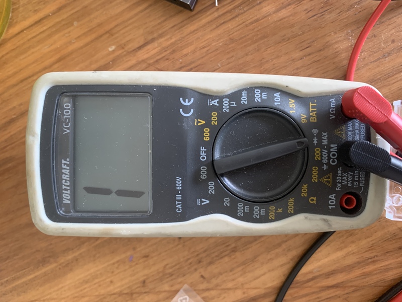
Then on the other end of the cables I soldered a small amount of lead and soldered them into pin headers. I borrowed the multimeter from the soldering station at XPUB to trace the keyboard with it.
I went home and I watched every YouTube video about tracing a keyboard matrix and didn't understand how because no one really explains exactly in a way you would explain to a Child. A baby should be able to follow a tutorial and draw up a keyboard matrix. Winner of best keyboard related channel:https://www.youtube.com/@snacksthecat/videos
Fred explained to me how to do this. We set the multimeter to the diode check setting and put one end to one of the pins at the top of the board. I have 16 keys so we all assumed 8 would be input pins and 8 would be output pins. Alas! I checked every key and wrote down which 2 pins responded to it.
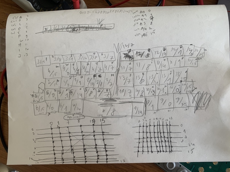
Fred told me to draw the keyboard and put the numbers like: 3/15 3/0 3/1 etc. He told me the finished schema will reveal which pins are ins and which ones are outs. But I didn't fully understand what that meant until I drew the actual matrix like the hashed diagram at the bottom of the photo of my paper above. On a 8-in 8-out schema it wouldn't matter but for me I had 10 ins and 6 outs.
I numbered my pins from 0: 0 1 2 3 4 5 6 7 8 9 10 11 12 13 14 15
I figured out that 2 3 4 5 6 9 10 11 12 13 are my ins and 0 1 7 8 14 15 are my outs. Which means if you press 2 + 0 you get a certain character :) If you're reading this it might seem either too easy or too difficult. The trick is: you have to do 1 yourself, break apart a keybaord, and then it will be clear how it works.
On the bottom right side of the paper I drew a version of this table which is the matrix:
| 2 | 3 | 4 | 5 | 6 | 7 | 8 | 9 | 10 | 11 | 12 | 13 | |
|---|---|---|---|---|---|---|---|---|---|---|---|---|
| 0 | touching #2 + #0 cables gives: "S" | touching #3 + #0 cables gives: "2" | 4+0: W | Z | SHIFT | etc.... | ||||||
| 1 | ||||||||||||
| 7 | ||||||||||||
| 8 | ||||||||||||
| 14 | ||||||||||||
| 15 |
which looked like this at the end on my code:
// {'S','2','W','Z','SHIFT','LEFT','/',' ','-',' '},
// {'D','3','E','X','DELETE','UP','.','P','0',';'},
// {'H','6','Y','B',' ',' ','N','U','7','J'},
// -{'G','5','T','V','SPACE',' ','M','I','8','K'},
// -{'F','4','R','C','BREAK','DOWN',',','O','9','L'},
// {'A','1','Q','SHIFT','CTRL','RIGHT','SHIFT','RETURN','=','X'}
Also made an ASCII version because one of the tutorials used this and I liked the
outcome of
this much better.I used ASCII-code.com for
reference. Here is a table of ASCII control characters:
115, 50, 119, 122, 15, 37, 47, 150, 0, 0,
100, 51, 101, 120, 127, 38, 46, 112, 48,0,
150, 54, 121, 98, 0, 0, 110, 117, 55, 106,
103, 53, 116, 118, 32, 0, 109, 105, 56, 107,
102, 52, 114, 99, 0, 0, 44, 48, 57, 108,
97, 49, 113, 15, 17, 0, 15, 13, 61, 120,
I ended up going back to the first tutorial I followed: https://forum.arduino.cc/t/keypad-data-entry-a-beginners-guide/660309
which is a keypad tutorial and changed the row numbers, column numbers and pins that
correlate to them.
The right Arduino code + The right micro-controller
The most important thing is not every microcontroller works with the keyboard library. Here is a list of arduino models that work with this library I snatched from the original documentation website:
| Board | Supported Pins |
|---|---|
| Leonardo | All digital & analog pins |
| Micro | All digital & analog pins |
| Due | All digital & analog pins |
| Zero | All digital & analog pins |
| UNO R4 Minima | All digital & analog pins |
| UNO R4 WiFi | All digital & analog pins |
| GIGA R1 WiFi | All digital & analog pins |
| Nano ESP32 | All digital & analog pins |
| MKR Family | All digital & analog pins |
And this is my final Arduino code that works(included libraries: Keypad, Keyboard, HID Buttons):
/* @file CustomKeypad.pde
|| @version 1.0
|| @author Alexander Brevig
|| @contact alexanderbrevig@gmail.com
||
|| @description
|| | Demonstrates changing the keypad size and key values.
|| #
*/

#include
#include   // Must import AFTER Keyboard.h
#include


const byte ROWS = 6; //four rows
const byte COLS = 10; //four columns
//define the cymbols on the buttons of the keypads
char hexaKeys[ROWS][COLS] = {
  115, 50, 119, 122, 15, 37, 47, 150, 0, 0,
  100, 51, 101, 120, 8, 38, 46, 112, 48, 59,
  104, 54, 121, 98, 0, 0, 110, 117, 55, 106,
  103, 53, 116, 118, 32, 0, 109, 105, 56, 107,
  102, 52, 114, 99, 0, 0, 44, 111, 57, 108,
  97, 49, 113, 15, 17, 0, 15, 8, 61, 13,
  };
// very important note: 13 as Carriage
//Return does not equal ENTER, you need to use 10 instead

byte rowPins[ROWS] = {A1,A2,A3,A4,A5,A0}; //connect to the row
//pinouts of the keypad, my cables snapped so the order is a bit messed up.
byte colPins[COLS] = {2,3,4,5,6,9,10,11,12,13}; //connect to the
//column pinouts of the keypad

//initialize an instance of class NewKeypad
Keypad customKeypad = Keypad( makeKeymap(hexaKeys), rowPins, colPins, ROWS, COLS);

void setup(){
  Serial.begin(9600);
  Keyboard.begin();
}

void loop(){
  char customKey = customKeypad.getKey();
  if (customKey){
    Keyboard.print(customKey);
  }
}
I also learned a lot from this tutorial which I recommend following because it helped me understand how the keyboard works.
https://www.instructables.com/64-Key-Prototyping-Keyboard-Matrix-for-Arduino/
Even though these .ino files just gave me a static from the keyboard, made me think I had a short somewhere like the other person who commented the same issue. It is not the case and this just doesn't really work unfortunately.
Waveshare screen
I then connected the keyboard with a USB to a Raspberry Pi(I don't even know the model it was old and clunky and for free)
I also bought this Waveshare display and connected that to the raspberry pi as well. This was a tad tricky and annoying I really don't want to do that again. But since I have learned that it is infinitely harder to reverse engineer screens than keyboards... so waveshare it is for now.
Final DisplayPhone